This guest post is by Ed Williams (edwilliams16). Interested in contributing an article? Contact Chris Hennes at chennes@freecad.org with your idea!
Much of FreeCAD scripting consists of creating objects and then placing them somewhere in 3D. For instance, we can create a default cube with
doc = App.ActiveDocument
cube = doc.addObject("Part::Box","Box")
doc.recompute()
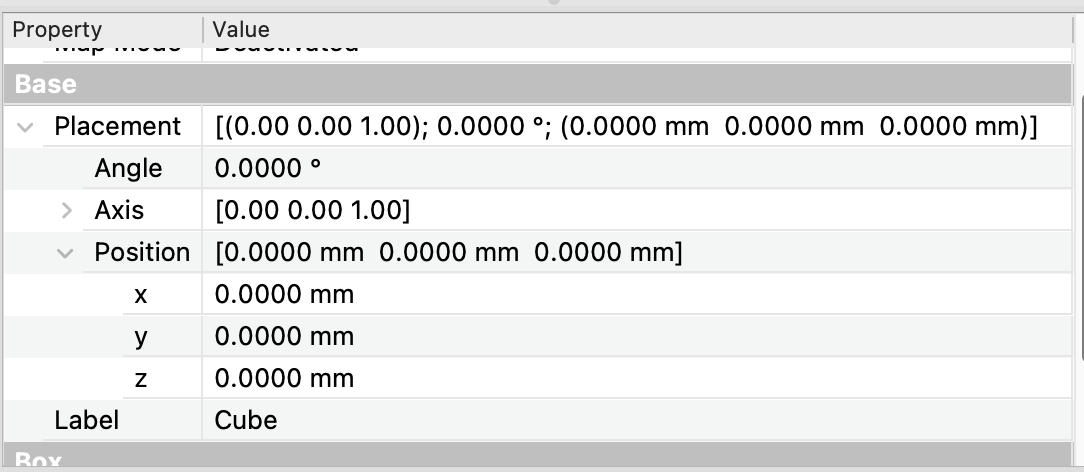
The resulting cube has its origin at (0, 0, 0) and is in its default orientation. To locate it elsewhere, without other modification, we can change its Placement property. Placement has two sub-properties: Placement.Base and Placement.Rotation. Placement.Base is the location of the cube’s origin and Placement.Rotation rotates the cube (with its origin fixed) into its orientation. If we examine the cube’s current Placement in the Data panel, we see

indicating an “identity” Placement. The Position (Base) is (0, 0, 0) and the Rotation is 00 around the z (0,0,1) axis. If now, for example, we change the cube’s Placement with
cube.Placement = App.Placement(App.Vector (10, 0, 0), App.Rotation(App.Vector(0, 0, 1), 20))
App.ActiveDocument.recompute()
this rotates the cube 20 degrees about its (0,0,1) axis and then translates it so its origin lies at (10, 0, 0), which we see reflected in the Data window.

Rotation(Axis, Angle)
Of the various ways of constructing rotations, perhaps the simplest to understand is
rot = App.Rotation(Axis, Angle)where Axis, the axis of rotation, is an App.Vector and Angle is the angle in Degrees. The (non-zero!) length of the Axis vector has no effect on its direction, so axes App.Vector(1, 1, 1) and App.Vector(2, 2, 2) represent the same direction. The axis argument of rot is stored as the property rot.RawAxis The Raw Axis is normalized to unit length by FreeCAD and is available as the property rot.Axis.
We see that in order to specify a rotation there are three degrees of freedom - two for the normalized direction and one for the rotation angle. However, the axis/angle representation is not unique. App.Rotation(App.Vector(0, 0, 1), 30), App.Rotation(App.Vector(0, 0, -1), 330) and App.Rotation(App.Vector(0, 0, 1), -330) all represent the same rotation. To test if two rotations are the same use rot.isSame(rot1, tolerance).
App.Rotation(vec1, vec2)
This represents a rotation that takes the direction defined by vec1 and rotates it into the direction vec2.
The axis of this rotation is normal to the plane defined by the two vectors and the angle is the angle between them.
vec1 = App.Vector(0,0,1)
vec2 = App.Vector(1, 0, 1)
rot1 = App.Rotation(vec1, vec2)
rot2 = App.Rotation(vec1.cross(vec2), Radian = vec1.getAngle(vec2))
rot1.isSame(rot2, 1e-14) #=> True
The rot1 form is more convenient than the equivalent, first principles, rot2 calculation, which assumes familiarity withe vector cross-product operation. The Radian keyword is used because the default angle argument is Degree.
Below we show this rotation acting on an object from the front and top views.
Fig (1) The App.Rotation(vec1, vec2) rotation front view.
Fig (2) The App.Rotation(vec1, vec2) rotation top view.
When we specify the final direction vec2 into which vec1 is rotated, we have only constrained two degrees of freedom, those of the direction specified by vec2, yet a general rotation has three degrees of freedom. What happened to the third? Suppose after our App.Rotation(vec1, vec2) rotation, we then spun our object around the vec2 axis. The resulting composite rotation would still have rotated vec1 into vec2, but the axes perpendicular to vec1 will end up in a different directions. This particular constructor therefore cannot create the most general possible rotation.
App.Rotation(vecx, vecy, vecz, string)
This is a more powerful constructor capable of creating arbitrary rotations.
A natural way to define a rotation is by its effect on the three coordinate directions. That is, provide as input arguments the three directions of the rotated x, y and z axes. However, since each direction vector has two degrees of freedom, this specification would provide six constraints on the three degrees of freedom a rotation possesses. First we note that only two directions need be specified because the third is derived from them by the right-hand rule. This still leaves one over-specification, which is resolved in the following manner.
from FreeCAD import Vector as V
rot = App.Rotation(V(1,0,0), V(0,0,0), V(1,0,1), 'ZXY')
What does this represent? string is the priority order of the axes.
-
Z is first: the Z-axis is rotated into the direction vecz:
V(1,0,1). (Two degrees of freedom used.) -
X is second: the rotated X-axis is placed in the plane defined by the
vecxandveczarguments, orthogonal tovecz. That is, the component ofvecxorthogonal toveczdefines the rotated X direction. (Uses one more degree of freedom.) -
Y is third: the
vecyargument is completely ignored. The new Y-axis is created forming an orthogonal triad with the new Z and X axes, constructed from the above by the right hand rule (in the direction Z x X, for those familiar with the vector cross-product).
Our example generates the same rotation illustrated in Figs. (1) and (2) above. Note how the (blue) z-axis and (red) x-axis in Fig. (1) change. The mapping from (xvec, yvec, zvec) to normalized direction vectors, in the second listed step above, is illustrated in Fig (3), the movie below.
Fig. (3) zvec and xvec inputs create the zdir xdir rotated normalized directions.
This rotation method forms the basis of the O-Z-X attachment mode for an object in FreeCAD.
App.Rotation(yaw, pitch, roll)
This is described and illustrated in the wiki. Here a rotation is described as the composite of three successive rotations. First a yaw about the z-axis, then a pitch about the rotated y-axis, then a roll about the **rotated **x-axis. More explicitly, here a rotated axis means that the axis is not the initial coordinate axis, but the axis that results from the prior rotations acting on the coordinate axis. Thinking of rotations of a body, the successive rotation axes are fixed in the body, not in space.
Compounding rotations
The action of a Rotation (or a Placement) on a vector is often called multiplication. We can write
rot*vector #or
rot.multVec(vector)
placement*vector #or placement.multVec(vector)
to compute the vector resulting from the transformation. For successive transformations, the ‘*’ is much tidier.
rot2 * rot1 * vector rot2.multVec(rot1.multVec(vector)) rot2.multiply(rot1).multVec(vector)all compute the effect of first rotating vector by rot1, then rotating the result by rot2. The result of applying two rotations is itself a rotation, likewise that of applying two placements is a placement. So the compound rotation or placement is just
rot_compound = rot2 * rot1and
placement_compound = placement2 * placement1There are three important things to note:
-
Both placements/rotations reference the
samecoordinate system. -
Unlike when multiplying numbers, the order matters! If you rotate an object around two different axes, you’ll generally get a different result if you reverse the order of operations.
-
The rotation
rot2*rot1means first rot1, then rot2. Think of them as function applications to understand the order.
To illustrate the second point, let us consider two easily visualized rotations R and S and apply them in opposite orders.
from FreeCAD import Vector as V
R = App.Rotation(V(1,0,0), 90)#90<sup>0</sup> around x
S = App.Rotation(V(0,0,1), 90)#90<sup>0</sup> around z
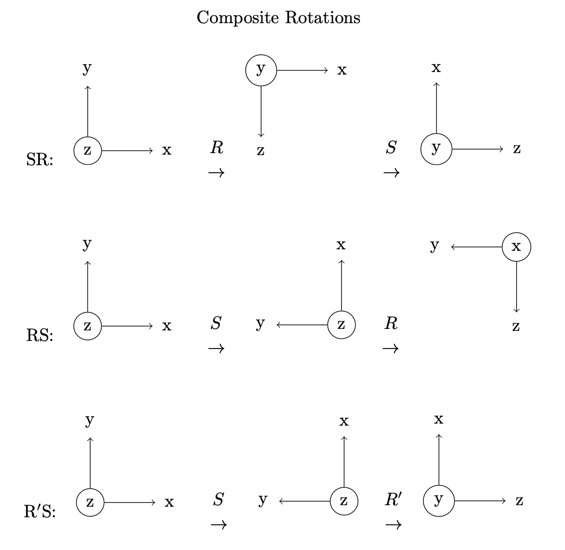
In the top row of the figure, we perform the rotation S*R . We rotate 900 around the coordinate x-axis, followed by 900 around the coordinate z-axis and show the effect on a axis triad.
In the second row, we perform the rotation RS and note that the result differs from that of SR.
The third row illustrates another important property of rotations. First we do the S rotation (900 around z), then we perform R’. R’ is again defined as 900 around x - BUT around the (already rotated) body x-axis, not the coordinate x-axis. This is as in the yaw-pitch-roll section above.
We see the result of R’S is the same as SR. This is in fact a general result that I will not attempt to prove here.
To perform a series of rotations in body coordinates instead of fixed coordinates, reverse the order of multiplications.
As an example, we can construct a rotation with a yaw-pitch-roll of 20, 30, 40 degrees, respectively, by post-multiplying the individual rotations.
from FreeCAD import Vector as V
yaw = App.Rotation(V(0,0,1), 20)
pitch = App.Rotation(V(0,1,0), 30)
roll = App.Rotation(V(1,0,0), 40)
ypr = yaw*pitch*roll
ypr_direct = App.Rotation(20,30,40)
ypr.isSame(ypr_direct, 1e-14)#=> True
Offset rotations
If we want to rotate an object about an axis that is offset from the origin, we use the three argument form of Placement:
App.Placement(base, rotation, center)This means
-
Rotate by
rotationabout an axis throughcenter -
Translate the result by
base
As an exercise, how could we have done this from first principles?
-
Translate by -
center -
Rotate by
rotation -
Translate back by
center -
Translate by
base
#sample data
base = App.Vector(50,0,0)
axis = App.Vector(1, 1, 1)
angle = 45
center = App.Vector(0, 10, 0)
rotation = App.Rotation(axis, angle)
#compare
ZeroRot = App.Rotation()
ZeroVec = App.Vector()
tr1 = App.Placement(-center, ZeroRot)
rot = App.Placement(ZeroVec, rotation)
tr2 = App.Placement(center, ZeroRot)
tr3 = App.Placement(base, ZeroRot)
offsetrot = tr3*tr2*rot*tr1
offsetrot_direct = App.Placement(base, rotation, center)
offsetrot.isSame(offsetrot_direct) #=> True
Inverse
Both rotations (rot) and placements (pl) have inverses, rot-1 and pl-1 which reverse their effect. These satisfy

where I is the identity rotation or placement, respectively.
Recall from the compound placement section, we found that R' * S = S * R. We could use the algebra of rotations to compute R' explicitly. Multiply both sides of the equation on the right by S-1, obtaining:
R’ * S * S-1 = R’ = S * R * S-1 In code, this becomes:
from FreeCAD import Vector as V
R = App.Rotation(V(1,0,0), 90)#90<sup>0</sup> around x
S = App.Rotation(V(0,0,1), 90)#90<sup>0</sup> around z
Rprime = S * R * S.inverted()
We find that Rprime is a 900 rotation around the (coordinate!) y-axis, in accord with the composite rotation figure above.
from math import degrees
degrees(Rprime.Angle) # => 90
Rprime.Axis # => App.Vector(0, 1, 0)
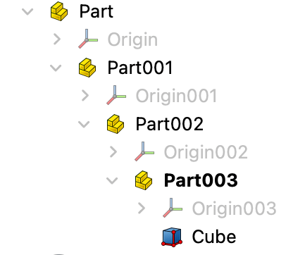
Being able to manipulate rotations (and placements) symbolically in this manner is a powerful tool. For another illustration of this, consider an assembly in which our object is contained in a sequence of nested container sub-assemblies.

The global placement of the Cube is the product of the placements that contain it. Referring to the Placements of Part, Part001, Part002, Part003 and Cube as pl0, pl1, pl2, pl3 and pl4 respectively, the global placement of the Cube is pl0 * pl1 * pl2 * pl3 * pl4. Suppose we want to change the global Placement of the cube to gpl by altering the placement of the Part001 sub-assembly, say by changing pl1 to pl1’. Then we know that

solving for the unknown placement pl1’ by pre- and post-multiplying by the appropriate inverses.